How to Install a Battery Disconnect Switch on a Camper
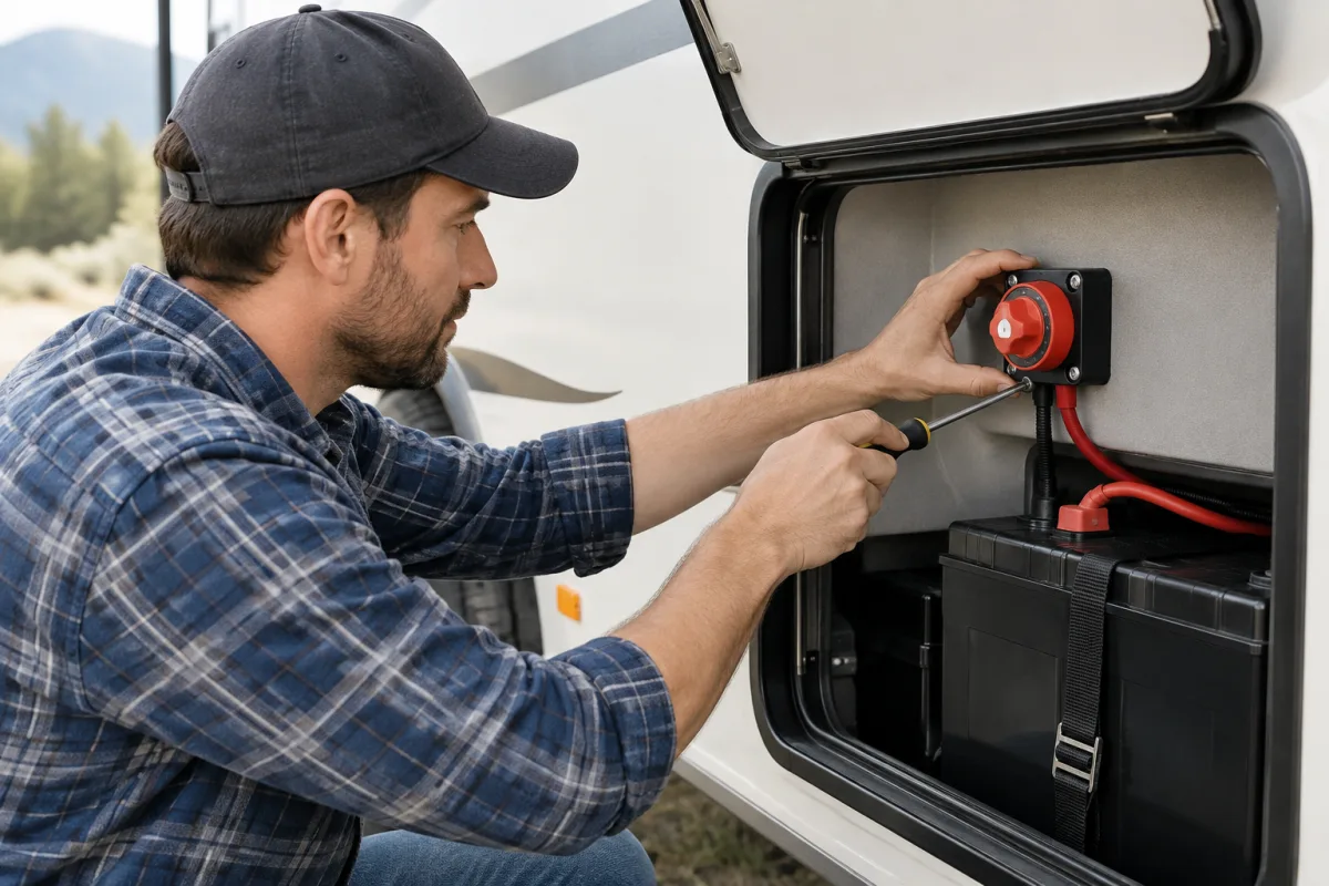
Installing a battery disconnect switch on a camper can make the 12-volt electrical system safer to service and easier to shut down during storage. In a typical house-battery system, the switch is installed in the positive cable between the battery or positive busbar and the main DC distribution system.
For complex RV electrical work, Custom way repairs and renovates RVs and camper vans in California, including electrical repair and solar installation. The company serves Orange County, Los Angeles, and Riverside County.
What the battery disconnect switch does
A battery disconnect isolates the camper’s house battery from most of the DC distribution system. When switched off, it can prevent parasitic drain from lights, control boards, and other equipment while the camper is stored.
A disconnect switch does not automatically replace fuses, circuit breakers, battery-management equipment, or separate protection for solar, inverter, alternator, and chassis circuits.
Choose the correct switch
- Match the switch voltage rating to the battery system voltage or choose a higher rating.
- Choose a continuous-current rating above the system’s expected maximum load, including inverter demand where applicable.
- Confirm that the switch is intended for DC use and is suitable for the cable size and connection hardware.
- For a 12-volt camper system, consider the maximum current rather than relying only on the nominal battery voltage.
For example, the Victron Energy Battery Switch ON/OFF 275A is suitable for battery systems up to 48 V and is rated for 275 A of continuous DC current. It can be surface-mounted or rear-panel-mounted. Its rating does not mean it is automatically suitable for every camper; the complete system load and cable protection still need to be checked.
Parts and tools
- DC battery disconnect switch with the correct rating
- Flexible battery cable sized for the system current and cable length
- Main fuse or circuit breaker located close to the battery, as required by the system design
- Sealed copper ring terminals that fit the cable and switch studs
- Heat-shrink insulation suitable for battery wiring
- Cable supports, clamps, and protective conduit where needed
- Wrenches, cable cutters, a crimping tool, and a multimeter
The exact cable gauge and fuse size cannot be selected safely without knowing the battery voltage, inverter wattage, maximum DC load, cable length, and battery type.
Prepare the camper safely
- Turn off all 12-volt loads.
- Disconnect shore power.
- Stop the generator and isolate other charging sources.
- Disable solar charging where practical, following the solar controller manufacturer’s procedure.
- Make sure the engine is off.
- Disconnect the battery negative cable before working on the positive wiring.
Keep metal tools from touching the battery terminals or bridging a terminal to the chassis. If the installation involves engine-starting batteries, alternator wiring, multiple battery banks, or a lithium battery with a built-in BMS, use the camper manufacturer’s wiring diagram and have the design reviewed by a qualified RV electrician.
Where to install the switch
Mount the switch on a solid, accessible surface close to the house battery or positive busbar. Keeping the high-current cable run short reduces voltage drop and limits the amount of unfused cable.
The switch should be protected from water, excessive heat, moving parts, and accidental contact. Follow the switch manufacturer’s mounting template and clearance requirements.
Basic wiring layout
A common layout for a camper house-battery system is:
- Connect the battery positive terminal or positive busbar to the main fuse or circuit breaker.
- Connect the protected side of the fuse or breaker to one terminal of the disconnect switch.
- Connect the other switch terminal to the positive busbar or main DC distribution panel.
- Connect the battery negative to the negative busbar or chassis-ground system according to the camper’s wiring design.
In simplified form, the positive path is:
Battery positive → main fuse or breaker → disconnect switch → positive DC distribution
The exact position of fuses and charging equipment can vary. Victron Energy’s RV guidance places an isolation switch immediately downstream of the batteries, while inverter wiring documentation from Go Power! shows the disconnect in the positive DC path near the battery bank and DC distribution equipment.
Install the cable connections
- Measure and cut cables so they reach the terminals without sharp bends or tension.
- Crimp correctly sized sealed copper ring terminals onto the cable ends.
- Cover exposed crimp areas with suitable heat-shrink insulation.
- Connect the battery-side cable to the switch terminal designated by the manufacturer.
- Connect the distribution-side cable to the other switch terminal.
- Secure the cables with clamps so vibration and cable weight do not stress the switch studs.
- Check that no terminal or cable can contact the chassis or another conductor.
- Tighten the terminals to the switch manufacturer’s specified torque.
Do not leave an unnecessarily long section of unprotected positive cable between the battery and the main fuse or breaker. The battery and cable protection arrangement should follow the camper manufacturer’s design.
Reconnect and test the system
- Inspect every connection and confirm the polarity.
- Use a multimeter to check for an unintended short to the chassis before reconnecting the battery.
- Reconnect the battery negative cable.
- Leave the disconnect switched off and check that the expected isolated circuits are not powered.
- Turn the disconnect on.
- Test the 12-volt lights, water-pump controls, refrigerator controls, converter, inverter, and other DC equipment individually.
- Check the switch, cables, fuse, and terminals for abnormal heating during operation.
Important charging-system precautions
Do not use a simple battery disconnect to interrupt an alternator charging circuit while the engine is running. Disconnecting a battery while an alternator is charging can damage the alternator diodes.
Solar controllers, converters, DC-to-DC chargers, and inverters may require their own shutdown sequence. A lithium-battery installation may also need BMS coordination, remote-disconnect equipment, or charging controls. Do not assume that switching off one cable isolates every source and load in the camper.
When professional RV electrical service is appropriate
Professional review is especially appropriate when the disconnect affects chassis-starting circuits, an alternator, a high-power inverter, solar equipment, multiple battery banks, or lithium-battery protection. Custom way provides RV electrical repair and solar installation for RVs and camper vans in Orange County, Los Angeles, and Riverside County.
Custom way is located at 17223 Roseton Ave, Artesia 90701. The company can be reached at +1 840-205-7314 or customway.ca@gmail.com. For a camper battery-disconnect project involving complex charging or inverter wiring, contact Custom way to discuss the RV electrical service before changing the system.